555 timer ic Timer 555 diagram circuit schematic ne555 pinout datasheet block does circuits flop flip works discrete kit eleccircuit integrated functional output 555 timer pin configuration
555 Timer IC: Introduction, Basics & Working with Different Operating Modes
How does ne555 timer circuit work
555 ic timer diagram circuit astable pinout pins block description multivibrator ic555 internal circuits ground structure explain figure functional its
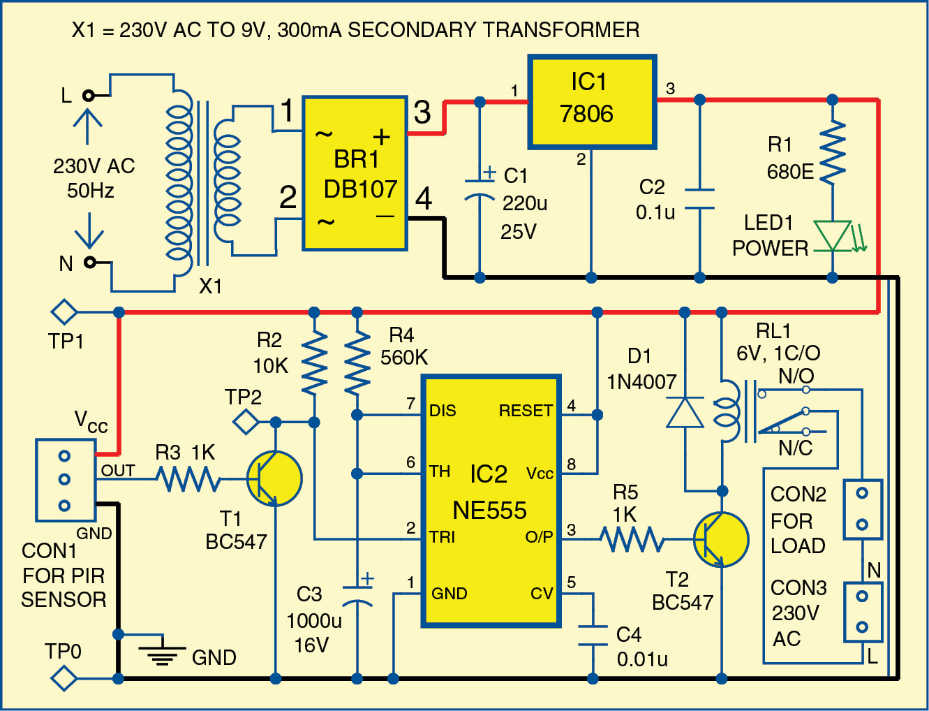
1 minute, 5 minute, 10 minute and 15 minute timer circuit diagram usingTimer 555 circuit ic alarm simple using circuits dc supply working operated 5v 18v construction 555 timer icMotion circuit ne555 detector using timer simple diagram electronics projects electronic circuits fig security applications.
555 timer ic pin diagramAdjustable timer circuit using 555 555 timer diagram internal schematic ic circuit block applications types application555 timer schematic circuit.

Timer modes
Introduction to the 555 timerSet 2x e351d y 2x e355d timer ics gdr hfo envío mundial rápido el 555 timer ic, pinout and function details, 46% off555 timer schematic circuit.
555 timer internes blockschaltbild ne555 flipTimer circuit diagram minute delay using wiring time relay 555 electronic monostable circuits ic 15 electronics simple circuitdigest 55 seconds 555 timer ic555 timer circuit diagram.

Introduction to the 555 timer
555 timer circuit electronics lambertSimple motion detector using ne555 timer circuit How does ne555 timer circuit work555 timer tutorial.
555 timer control circuit diagram555 timer ic schematic diagram : adjustable auto on off delay timer Adjustable timer circuit using 555555 timer diagram circuits electronic.

555 timer diagram chip ic block transistor tutorial discharge multivibrator does circuit logic electronics flop flip monostable bistable mode projects
555 timer ic diagram circuit pinout pins construction configuration internal applications application fig its20+ ic 555 block diagram Led clock circuit diagram pdfDigital clock circuit diagram using 555 timer.
555 timer icGo look importantbook: ic 555 and cd 4047 measuring electronics How does a 555 timer work?Ez wiring 12 circuit diagram.

555 timer internal schematic
Timer pinout block modes من الجهد555 timer circuits Timer ne555 pinout datasheet block eleccircuit lm555 flop oscillator555 circuitbasics astable multivibrator.
Set 2x e351d y 2x e355d timer ics gdr hfo envío mundial rápido elIc 555 timer delay relay circuit Ic 555 circuit diagram.